Blocks levels - please discuss!

colB
colB Member Posts: 762 Guru

I'm back working on a bunch of Blocks, and the same annoying questions is still grinding away in the background.

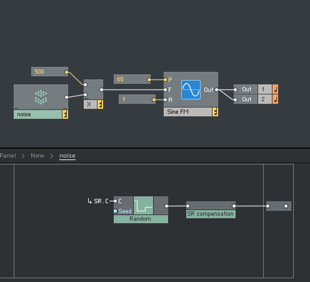
What level should I/we be aiming for in terms of oscillator output, FX output... etc. (and assuming in terms of inputs). The Framework documentation says we should keep within a limit of -1..1.Factory Oscillators are -0.66..0.66.Some UL and 3rd party are -1..1, others push beyond that limit, or are well within.

So far my thoughts are:

-1..1 would be nice and simple, and the louder things are the better they sound... however, -1..1 leaves no headroom whatsoever, so sending that into e.g. a softclipper means the clipper must have input attenuation, or subtle clipping will be impossible...

-0.667..0.667 seems like a good compromise - there is some built in headroom for FX, saturation, mixers etc.

going with -0.5..0.5 might be even better - more headroom, and there's really no issue with noise floor in a FP digital audio path... so why not?

But for FX, we have to make some assumptions about input signal level, or have extra controls all over the place - e.g. a wavefolder will have an input amplitude threshold where folding starts. If that's set too high, then a wave at -0.5..0.5 will need a boost before it will do anything, and when it does, the output will be somewhat louder than that input waveform... but if it's too low, then some Blocks with hot outputs will cause some folding even at minimum... not ideal!

So I'm thinking maybe I will target a magnitude of 0.667 as an output for everything other than amplifiers and other boosters, then at least there will always be headroom... and just assume others do the same... then if there are problems with other 3rd party blocks due to hot outputs, then that's on them? still far from sure though!

It's interesting that in Eurorack, there is no hard standard, but for the most part stuff (oscillators, envelopes, LFOs etc.) runs at 10v peak to peak, within a system that is 24v peak to peak... some things (mostly CV) go 0..10, some -5..5, some 0..5... Whatever, there is generally a lot more audio headroom than in Blocks. That's nice for stuff like subtle saturation staging.


Example:

Lets say you create a tanh saturation Block, targeting an output of -1..1 maximum. If you send a -0.6..6 signal into that, the saturation is not going to be particularly subtle.

If a user wanted to use multiple instances of that throughout a patch to add subtle warmth/distortion, they would have to have multiple VCAs or Mixers to attenuate significantly between stages to achieve that goal... not immediately obvious.

------------------------------------------------------------------

So... any thoughts on this conundrum? what do other folk do? are UL things mostly -1..1 or -0.667..0.667?... do folk even stick to the Blocks Framework specs?

«1

Comments

  • bolabo
    bolabo Member Posts: 97 Advisor
    edited February 2023

    For me I think my main consideration when thinking about this is that in a virtual modular setup you tend to freely mix audio rate signals and modulation signals. And so ideally all signals should operate within a similar 'virtual voltage' range. The NI factory Bento LFO is -0.5..0.5 or 0..1 in unipolar mode, the Bento Oscillator as you mentioned is -0.666..0.6 and the envelope is 0..1

    I think most of the Toybox stuff is a little higher, -1..1 for oscillators or 0..1 for modulation, but this had a lot to do with the Toybox sequencers being driven by a 0..1 'position' signal so I wanted to normalise everything to -1..1

    I added a soft clipper (set clip above -4..4) to most of the blocks that I kind of treat as the equivalent of the 24v rail in Eurorack, without which runaway feedback can occur with racks that have gain in their feedback paths.

    I tend to think about '-1..1' as being the equivalent of the Eurorack 10v peak to peak, assuming that voltages can and do often go above -1 and 1, and I then turn down Reaktor's master volume to avoid any clipping at the output. I also turn down inputs on mixer blocks when summing together oscillators to try to keep the output of the mixer around -1..1. I also tune the saturation in filters etc to kick in musically a little above -1..1

    I recon the Bento block values are a pretty good guide to follow.

  • colB
    colB Member Posts: 762 Guru
    edited February 2023

    That's an interesting perspective thanks. It got me thinking about some potential problems...

    limiting to a -1..1 range as a hard rule for interconnections, is a very useful idea, it means you have a guarantee at the input of your Blocks, and that magnitude 1 boundary is very useful in various ways. You might have a process that relies on e.g. mapping the input to a curve by squaring it or cubing it - this stays within that -1..1 range as long as the input is in range... you need to put a clipper in front as a precaution... but it just works well in general... similarly for audio its useful to be able to assume a maximum peak value at input...

    But what happens when there is an already hot signal that then goes through something like a DC filter... if its peaks were -1..1 already, any change in DC offset can throw it outside of that range.. one way or the other... so you then get clipping at Block inputs, or worse if there is no protection clipper... Something like a pulsewave with more extreme pulsewidth settings...

    Maybe more insidious example would be a square wave at -1..1 going into filter. The Gibbs phenomenon means that (depending on settings) you will get overshoot/ringing at the transitions, so the output will exceed the -1..1 limit. Some Blocks receiving this signal might hard clip it mercilessly, causing some aliasing artefact. Cant expect the filter Block to 'handle' this issue, because whatever you do will effect the audio quality for signals that are not already at the peak, and also cost cpu - imagine if every Block needed an oversamples ILO at ever input :).

    I guess the 0.66 magnitude of bento is probably enough headroom for these scenarios... but are there others :) and why not go to 0.5 magnitude? what are the downsides?

  • Chet Singer
    Chet Singer Member Posts: 56 Advisor

    Good subject. This is something that probably would've been good for NI to address more explicitly. For example, the Nord modular oscillators had output levels that were 1/4 of full scale, or -12 dB from the DSP chip's arithmetic overflow point. It was clear in their documentation that if you added more than four full-scale oscillators together you would clip the signal.

    In blocks, I assume that all oscillators send out +/- 1 signals and things will easily clip unless I keep an eye on things.

  • colB
    colB Member Posts: 762 Guru

    Here's what the Framework doc says:

    Just as all connections between Blocks should be audio rate signals, the value range of those signals should always remain within a range of [-1, 1]. Again, this serves to ensure compatibility across the entire framework.

    This seems nice and clear - keep within -1..1 to ensure compatibility!

    however then they muddy the waters with:

    There remains still the possibility to exceed that range, either by mixing multiple signals together, or by simply applying excessive amounts of gain to a signal. Never the less, the [-1, 1] range should be considered the standard operating range at all inputs and outputs.

    This is less clear, suggesting that mixed signals might exceed -1..1, but it's not precise language, so the meaning is ambiguous. Do they mean you can exceed the range within a Block, or does it mean that its OK to output a signal outside of the range from something like a mixer or FX Block?

    and there's more ambiguity:

    Signal polarity or bias is less of a concern, and it is perfectly acceptable for signals between Blocks to be offset or entirely unipolar. It is however inadvisable to connect a biased signal directly to the main output, as this could potentially cause damage to monitoring equipment in the case where the audio interface used does not have an AC coupled output

    I would like to interpret this as 'bias or DC offset is acceptable as long as the resulting signal is still within the -1..1 range, but it definitely doesn't make that clear, particularly in the context of that second paragraph. One could interpret this as meaning that it's ok to have a signal that is -1..1, then add a DC offset resulting in say a signal in the range 1..3.

    This ties in with my example where a pulse wave at -1..1 peaks through a DC filter would result in values outside of the -1..1 range...

    I suppose the problem is that there's really nothing the designer of that filter can do, it really depends on not generating a -1..1 pulse wave with narrow PW setting in the first place...

    Mixers are easier - just have clipping built into the mixer. That's still problem with -1..1 source signals (it's fine if there is an input attenuator per input - but there might not be...) There's no headroom, so even with one input signal, there will be clipping unless its a hard clipper... no option to have soft clipping unless every input has an explicit attenuator control, and maybe also some sort of clipping lamp...

  • Studiowaves
    Studiowaves Member Posts: 451 Advisor
    edited February 2023

    Think dynamic range for starters. How much is available and what area of the dynamic range allows enough headroom to optimize your levels to reach but not exceed the available dynamic range. For starters the overall dynamic range in the digital realm is 6db per bit. So if the blocks are 32 bits then your dynamic range is 512 db. That's a lot of dynamic range compared to what a human can detect. Most people can't hear anything that is 80 db down. So if the blocks are 32 bits it would seem you've got a huge area to work with. So now, take a look at the actual number of bits required to produce an undistorted sound from a pure sound wave. Lets assume we have a sine wave with where the distortion is 80db down. Do the math and that would be a minimum level for your blocks. It's close to the value of a20 bit signal. Which gives you 12 bits of headroom or 72 db of headroom. That's enough headroom to kill a pair of speakers or you ears if your listening to something where the distortion is 80 db down but the volume out of the speaker is at an average listening level. So a simple formula for determining the headroom is to ask yourself, how loud is full acoustic volume and what volume is the average listening level. Some think 85 db of sound pressure is their perfect listening level as they can handle 100 db for extremely loud parts. Others think they can handle 110 db of sound pressure. Have a look at the charts that cause hearing damage. Your asking for it at 110 or more db of sound pressure. So then you ask about saturation blocks. It simple, put a volume knob on it's input and it's output. It's kind of nice to have a drive knob that increases or decreases the input while internally inverting the same amount after the saturator. This way you increase the saturation without increasing the output. However saturation typically reduces energy and a simple output gain comes in handy to restore the lost energy. I've subtracted the rms intput from the rms output value of saturation circuits to come up with the necessary gain following the saturator to keep the same energy level the same. So basically you hear the harmonic changes yet perceive roughly the same volume. So how many bits are default blocks? Find that out a go from there. I always think in terms of decibels. What your asking is nothing standard electronic equipment does. Nearly everything has an input and output gain control. They always indicted the gain change in decibels, never values.

  • colB
    colB Member Posts: 762 Guru

    That's not really the area I was hoping to discuss. My fault for being to general with the thread title :)

    I'm really wanting more clarity relating to design compromises not engineering specifications. I don't think the headroom of a 32 bit audio path is particularly relevant to the choice between -1..1 and -0.5..0.5 or -0.667..0.667

    (It's an interesting topic for another time though. Does the mantissa/exponent system in 32 bit floats still follow the 6db per bit rule? Wouldnt we have to consider precision and resolution separately?...)

  • errorsmith
    errorsmith Member Posts: 25 Helper

    i would approach this more from the perception side and not as a hard measurable standard. i also would take the standard as a rough guideline, not as a rule book. eg having oscillators at -.1 to -1 or -10 to 10 is clearly not according to the guideline. around -1 to 1 is alright.

    e.g. lets say you have an oscillator that can morph between different standard waveforms. i would find it totally acceptable to have a saw between -1 and 1 and the rest of waveforms with amplitudes that would sound good when you morph between the waveforms. that could mean that the 50/50 pulsewave is between -.5 and .5, as it then has the same energy as the saw.

    having a separate saw and pulse osc, i would choose -1 to 1 for saw (i guess saw is my standard), and would find it both acceptable to have the pulse at -1 to 1 or -.5 to .5. i would connect the modules in a useful manner (in this case with an oscillator mixer), and see if the set level ranges sound right.

    imo if a module's function depend on the input volume it should have a manual 'drive' or 'input level' control.

    eg saturation should have a 'drive' manual control, which can also attenuate. this way the user can set the desired amount of saturation. concerning the output range of the saturator, i would use -1 and 1 for hard clipping and s-shape saturators that reaches full saturation rather quickly. for saturator shapes that slowly reach full saturation i would choose a higher ceiling. my guidance would be again, also with ceiling of asymmetrical shapes : what sounds good if i switch/blend between different saturation curves.

    effects usually have ways to set them up to pass the signal unaltered (like an amount control). in this case the amplitude shouldn't be altered as well imo so when you insert the fx in the signal path it sounds the same as before. if you increase the fx amount the overall level might get increased and over the -1 and 1 standard. that is ok. just design the fx in a way so the possible level change sounds right when you increase the fx amount or change other parameters. you might need to auto-adapt the output level when changing certain parameters.

    same is true for filters. if set to flat the amp should be 1. again if you then change the filter parameter and crank the resonance just make sure that the changes sound musical. if your ears say it got too loud you might want to use saturation to limit the resonance and /or decrease the output level if reso goes up etc

    i wouldn't clip signals or use a gain compensation just to comply to the standard -1 to 1. also not in a mixer. clipping for character in a mixer is another question.

    with FP resolution within reaktor there is no risk of clipping when the signal gets hotter than -1 to 1. so it doesn't matter if the levels go up in a module. when the input level matters for a module, then there is a manual input level control. when you want to mix signals, you can use the level controls of the mixer to adjust level differences. before the signal goes out to the soundcard, there is a master level control or similar.

  • Studiowaves
    Studiowaves Member Posts: 451 Advisor

    I wasn't really talking about specs, just the areas we should be working in to optimize the clarity. Sort of the same thing as the sample rates we choose. Just saying to optimize levels so peak levels max out the number of bits we have to work with at some point in the chain. You wouldn't want your peak level to be 24 bits down just like you wouldn't want the sample rate to be 12k when your using frequencies up to 24k. Seems to me it would simplify matters if +-1 were the true clipping levels of any block. If it were standardized per block it would always give us a frame of reference knowing we are minimizing quantization errors if our signals reach peaks of plus or minus 1.

  • colB
    colB Member Posts: 762 Guru
    edited February 2023

    That's an interesting point of view, and some good advice thanks. I don't completely agree about using perception as a guide though.

    Here's an actual real world example of the problem of using perception as the guide, particularly in the context of Blocks where there should be no distinction between 'audio' and 'control' signals:

    Noise is something that is commonly used as both an audio source and a control source... sometimes to enhance the attack of a sound for percussive effect, or to provide some grit, or texture in pads etc... it can also be used in a modular context to provide note values or modulations values particularly when combined with sample and hold.

    The factory sample and hold Block (Blocks base Bento Box S&H) internally uses the factory 'white noise' module for its noise component. That module has an internal SR compensation. This is because as you change the sample rate, the perceived volume of white noise changes. As the sample rate rises, more of the noise energy is above the range of human hearing, so the volume seems to drop. This works great when using the module as an audio source, however it means that if you use it as a sample and hold source, the output is scaled by the compensation such that a patch created at 192Khz might perform quite differently at 48Khz. There is no way for a non-technical user to guess that this could even happen...

    It's a slightly different situation, but I really think that trying to massage signals like square and saw to adjust for the perceptual results is a job for the musician building the patch, not for the designer of the instruments. You won't see this sort of second guessing in Eurorack hardware for example (at least not in my experience).

    The other stuff, about the choice of a base standard for signal peaks is more difficult, and you have a very good point about not worrying about clipping to -1..1.

    same is true for filters. if set to flat the amp should be 1. again if you then change the filter parameter and crank the resonance just make sure that the changes sound musical. if your ears say it got too loud you might want to use saturation to limit the resonance and /or decrease the output level if reso goes up etc

    To me this seems like a very good reason to keep source signals well inside the -1..1 limit. If a saw wave is processed through a filter with settings that lower the perceived volume, then if the original waveform was e.g. in the range say -0.5..0.5 boosting the output or resonance of the filter to match the perceived levels doesn't have to take the resulting waveform outside of spec!

    The whole philosophy of Blocks is that users should just be able to patch stuff together in whatever way they can dream of and it should work. When sound sources are outputting signals already at peak level, that necessitates extra 'technical' controls on some other Blocks... Reaktor is already seen by many as overly complex and too technical. It's better if it's simple and just works. That's never going to be completely true, but we should try to aim for that.

    I suppose another option would be just to shelve technologies that can't gracefully handle out of spec inputs, or at least not use them for Blocks. Seems a shame though!

  • errorsmith
    errorsmith Member Posts: 25 Helper
    edited February 2023

    interesting, i just learned that the perceived loudness of non amp compensated white noise varies with samplerate. i guess i have the sample rate pretty constant at 44.1 :) good to know. thanks!

    i think the bento box sample and hold shouldn't use the amp compensation. it's a bug. the noise is only used to be sampled and hold, so the only rate that matters is the rate of the gate. and that doesn't change if you change the sample rate.

    (as i just learned) noise should be amp compensated when heard directly as an osc and also when used as modulator (without sample & hold). i just tried it like this..

    ..and the compensation needs to be on in order to sound the same at different sample rates.

    but i see your point. connect this noise oscillator to the input of the Bento S/H and the amp of the output depends on the sample rate.

    An ok compromise would be to bandlimit the noise like that..

    .. or would dogs complain that there is not enough high end in there? :) this gives similar results at different sample rates also if sampled and held.


    It's a slightly different situation, but I really think that trying to massage signals like square and saw to adjust for the perceptual results is a job for the musician building the patch, not for the designer of the instruments. You won't see this sort of second guessing in Eurorack hardware for example (at least not in my experience).

    i think my suggestion for having pulse osc at .5 amp and a saw at 1 is a good one when you consider morphing or switching between the two shapes. a modulation of the shape should sound smooth. a patch is not just a preset set in stones so a manual switch between the shapes as part of live action or automation should sound nice.

    having a single pulse oscillator (without shape switching or morphing) i would argue that -1 and 1 would be the preferred choice. the argument that it should fit the standard is more valid here than the issue that the pulse is 6 dB louder this way than the saw at -1..1. the user can set the volume with a mixer.

    yeah this issue is a bit messy. and there are often trade offs.

    i am curious, are there other examples of 'out of standard' problems with blocks that you noticed?

  • colB
    colB Member Posts: 762 Guru

    i am curious, are there other examples of 'out of standard' issues with blocks that you noticed?

    Not really in terms of publicly available Blocks. But I've had experiences of spending hours tuning algorithms to then have them perform very poorly when testing with other Blocks, and discovering the reason is the different input amplitudes.

    i think the bento box sample and hold shouldn't use the amp compensation. it's a bug. the noise is only used to be sampled and hold, so the only rate that matters is the rate of the gate. and that doesn't change if you change the sample rate.

    Yes, I reported it as a bug, and it was acknowledged, but I think it is not important - the difference it makes are not significant enough, and will be rare anyway. It's just an interesting example. I discovered it when I was working out compensation macros for red, blue, pink and purple, so I was focussed on noise related subtleties. I realised that this would be a potential problem for certain use cases, so I looked at the Factory block to see how they had handled it :)

    Filtering doesn't actually work. but it changes the distribution from uniform to more gaussian (I think because of the feedback in the filter), so the outliers are rarer. You have to wait a while to get the higher magnitude values, but they will be there.

    An alternative solution is just to roughly down-sample the clock that's driving the process. As its noise anyway, artefacts don't seems to be an issue, and this sorts out the problems with compensation very cheaply. This way we get noise that works for audio at different sample rates, and also works as a control signal. Only folk with golden ears will tell a difference... so not me!

    Maybe in some use cases this is also problematic, but worth testing anyway :)


    Back on topic. After reading your post again, and also thinking about hardware, I think its a shame how the specification is defined. It might be better if -1..1 was defined as a guideline for signals, and then another threshold was defined as a hard clipping point something like -4.0..4.0. That was there is lots of headroom, users can push up levels within a patch, more options for creativity with gain staging, saturation etc...

    Maybe better would have beeen -1..1 being the hard clip level, and -0.25..0.25 rule of thumb for signals or something... just to keep in line with the 0.1 per octave scaling for note values.

    Anyhow, I'll be choosing between the bento levels or -1..1. I think it will be bento style unless I find a compelling reason to switch to -1..1

  • errorsmith
    errorsmith Member Posts: 25 Helper
    edited February 2023

    But I've had experiences of spending hours tuning algorithms to then have them perform very poorly when testing with other Blocks, and discovering the reason is the different input amplitudes.

    it sounds like that a 'input level' or 'drive' control would be the solution for this, no?

    BTW: how do you quote individual lines in this forum? can't figure it out.

    Filtering doesn't actually work. but it changes the distribution from uniform to more gaussian (I think because of the feedback in the filter), so the outliers are rarer. You have to wait a while to get the higher magnitude values, but they will be there.

    is that really noticeable with a high cutoff like this?

    An alternative solution is just to roughly down-sample the clock that's driving the process.

    i thought of that too, but that wouldn't work with sample-rates below 44.1 i fear.

    Maybe better would have been -1..1 being the hard clip level, and -0.25..0.25 rule of thumb for signals or something... just to keep in line with the 0.1 per octave scaling for note values.

    personally i wouldn't like any hard clip level at all. to me that would be like emulating the bad side of analog, where levels are clipped to the rail voltages -12 .. +12 with eurorack. there was a time when the reaktor vst was clipping to -1..1. the argument was that the standalone would clip as it passes the sound to the soundcard directly, so should the vst. Otherwise there would be a difference in sound between standalone and vst. I was relieved that the clipping was turned off. when there is an unwanted distortion somewhere, i don't want to chase a hidden clipping inside one of the modules in the chain. And i haven't read a compelling argument for this clip standard.

    i understand that it would be good for you as the designer of a module to know what the incoming levels are. but the openness of a modular system makes it really difficult to predict that.

    an example with your -1..1 hard clip suggestion. mix 4 .25 amp signals together, then you are already at the max of -1..1. send it to a filter and you have zero headroom for the resonance.

    it's also overkill to have a clipper, better a antialiased softclipper in all modules which can increase levels.

    it's the big advantage of a pre wired synth. there you can make sure that levels match in a musical way. eg setting a good sensitivity of a nonlinear filter for the possible soundmix going into it etc.

  • Studiowaves
    Studiowaves Member Posts: 451 Advisor

    Mixing sound is an add/subtract situation. The masking effect pretty much spells it all. On thing can drown another out. One of that main reasons ducking is used. Simple solution to keep one thing from masking the sound of another. Headroom is merely a convenience to allow for adding extra eq or handling sharp peaks for snare drums and what not. Hard clipping produces overtones, Not necessarily a bad thing, it depends on what is getting clipped. Want to use 8 bits for a sound, go for it. Drummers get excited, they speed up. Boosting the volume and brightness of everything, now your rockin'. Congratulations, you've created a monster. Just what the part called for. Momma starts yelling, turn it down, Uh oh, run away. lol

  • ANDREW221231
    ANDREW221231 Member Posts: 295 Advisor

    BTW: how do you quote individual lines in this forum? can't figure it out.

    its a simple copy/paste, and then you type in an ">" afterward, and press enter. usually requires hitting enter twice, actually

  • errorsmith
    errorsmith Member Posts: 25 Helper
    edited February 2023

    thank you andrew!

    its a simple copy/paste, and then you type in an ">" afterward, and press enter. usually requires hitting enter twice, actually

    with a blank before the ">" it worked for me. great

Back To Top